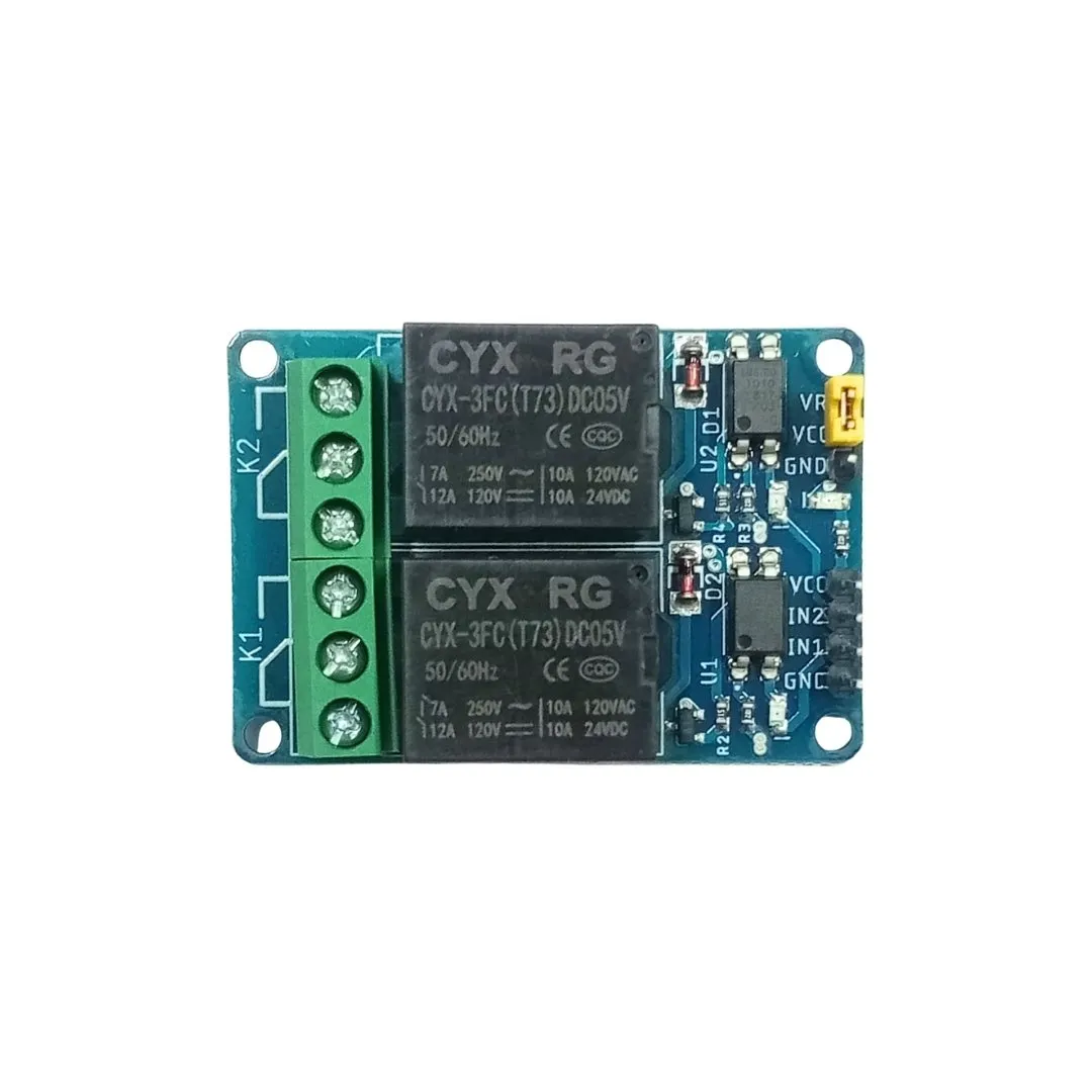
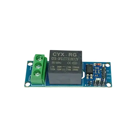
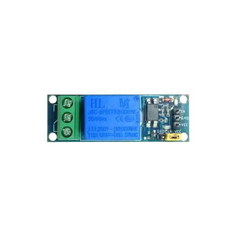
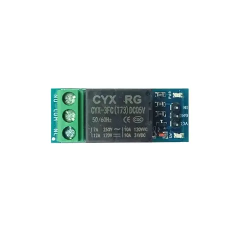
Relay Module 5V 2 Channel contains two relays that are electrically isolated from the controlling input. The relays can be used to switch higher voltage and current loads than a microcontroller can traditionally accomplish. ADIY 5V Dual Channel Relay Module be used to control various appliances, and other equipment with large current. It can be controlled directly with 3.3V or 5V logic signals from a microcontroller (Arduino, 8051, AVR, PIC, DSP, ARM, ARM, MSP430, TTL logic).
[vc_row][vc_column][vc_column_text woodmart_inline=”no” text_larger=”no”]
2 Channel 5V Relay Module is an interface board and can be controlled directly by a wide range of microcontrollers such as Arduino, AVR, PIC, ARM, and so on. With digital outputs to control larger loads and devices like AC or DC Motors, electromagnets, solenoids, and incandescent light bulbs.
This module is designed to be integrated with 2 relays that it is capable of controlling 2 relays. 5V 10A 2 Channel Relay Module Shield for Arduino ARM PIC AVR DSP Electronic relay is a 24V 2-channel relay interface board. If you have ever had a project that required an interface with a high-power device that needed AC or DC voltage and high current levels you have probably already discovered that attempting to control those devices directly with your Arduino, Raspberry PI or other Microcontrollers/Microprocessors can be a real challenge. This board is designed to interface easily with your 5V IOs without consuming much current on your IO pins.
Features: 5V Dual Channel Relay Module#
- It can control both AC and DC appliances such as Solenoids, Motors, lights, fans, etc
- High-quality screw terminals (Terminal Block) provided (C, NC, NO) for quick and easy connection
- A freewheeling diode to protect your microcontroller
- Input Signal Pin connected to Burg stick for easy accessibility led status indicators to indicate the relay ON/OFF status
- Mounting holes provided
- Signal input with a high-level signal, the common and often start conduction
- The relay can directly control all kinds of equipment and load
Specifications: 5V Relay Module 2 Channel#
- Channel – 2
- Operating Voltage(VDC) – 5V
- Current Capacity at AC250V – 10A
- Current Capacity at DC30V – 10A
- Dimensions: Length×Width×Height (mm)=34×50×16
Pin Description:5V Relay module dual Channel#
- C=Common: This is the common terminal. This terminal will be connected to either of other 2 terminals (NO or NC) based on the state of the relay.
- NO=Normally Open: As the name indicates this is a normally open terminal, i.e. if the relay is not energized (not ON), this pin will be open. We can say that the switch is OFF by default and when the relay is energized it will become ON.
- NC=Normally Close: As the name indicates it is a normally closed terminal, i.e. if the relay is not energized (not ON), this pin will be closed. We can say that the switch is ON by default and when the relay is energized it will become OFF.
How To Word on 5V Dual Channel Relay Module#
The dual-channel relay module can be used to switch mains-powered loads from the pins of the microcontroller. Since there are two channels on the same board, two separate loads can be powered. This is useful for home automation.
The loads can be connected as follows:
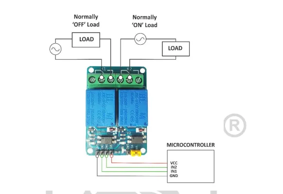
In this diagram, the relay on the left (channel 1) is connected in a regular fashion with the load and source going between common and normally open, so when the relay is activated, the load is powered. On the right channel (channel 2), the load and source are connected between common and normally closed, which means that the load is powered by default till the relay is activated.
If the load is connected to the normally closed contact, then the input polarity ‘reversal’ can be fixed – the load is powered on when the input is high, and the load is powered off when the input is low. This method, however, wastes some current since the relay coil draws current when the load is switched off.
Dual-Channel Relay Module Basic Troubleshooting#
If either of the relays does not turn on:
- The contacts might be welded due to overcurrent/arcing. Shaking the module firmly might help unstick the contacts
- The driver circuitry might have been damaged due to overvoltage.
- Input polarity might be incorrect.
- The jumper might not have been moved to the correct position.
Applications: 5V Relay Module 2 Channel#
- To control high voltage
- To control high current loads such as motor
- To control solenoid valves
- To control lamps and AC load
Resources:
Package Includes: 1 x 5V Dual Channel Relay Module
[/vc_column_text][/vc_column][/vc_row][vc_row][vc_column][vc_column_text woodmart_inline=”no” text_larger=”no”]
2 Channel 5V Relay Module is an interface board and can be controlled directly by a wide range of microcontrollers such as Arduino, AVR, PIC, ARM, and so on. With digital outputs to control larger loads and devices like AC or DC Motors, electromagnets, solenoids, and incandescent light bulbs.
This module is designed to be integrated with 2 relays that it is capable of controlling 2 relays. 5V 10A 2 Channel Relay Module Shield for Arduino ARM PIC AVR DSP Electronic relay is a 24V 2-channel relay interface board. If you have ever had a project that required an interface with a high-power device that needed AC or DC voltage and high current levels you have probably already discovered that attempting to control those devices directly with your Arduino, Raspberry PI or other Microcontrollers/Microprocessors can be a real challenge. This board is designed to interface easily with your 5V IOs without consuming much current on your IO pins.
Features: 5V Dual Channel Relay Module#
- It can control both AC and DC appliances such as Solenoids, Motors, lights, fans, etc
- High-quality screw terminals (Terminal Block) provided (C, NC, NO) for quick and easy connection
- A freewheeling diode to protect your microcontroller
- Input Signal Pin connected to Burg stick for easy accessibility led status indicators to indicate the relay ON/OFF status
- Mounting holes provided
- Signal input with a high-level signal, the common and often start conduction
- The relay can directly control all kinds of equipment and load
Specifications: 5V Relay Module 2 Channel#
- Channel – 2
- Operating Voltage(VDC) – 5V
- Current Capacity at AC250V – 10A
- Current Capacity at DC30V – 10A
- Dimensions: Length×Width×Height (mm)=34×50×16
Pin Description:5V Relay module dual Channel#
- C=Common: This is the common terminal. This terminal will be connected to either of other 2 terminals (NO or NC) based on the state of the relay.
- NO=Normally Open: As the name indicates this is a normally open terminal, i.e. if the relay is not energized (not ON), this pin will be open. We can say that the switch is OFF by default and when the relay is energized it will become ON.
- NC=Normally Close: As the name indicates it is a normally closed terminal, i.e. if the relay is not energized (not ON), this pin will be closed. We can say that the switch is ON by default and when the relay is energized it will become OFF.
How To Word on 5V Dual Channel Relay Module#
The dual-channel relay module can be used to switch mains-powered loads from the pins of the microcontroller. Since there are two channels on the same board, two separate loads can be powered. This is useful for home automation.
The loads can be connected as follows:
In this diagram, the relay on the left (channel 1) is connected in a regular fashion with the load and source going between common and normally open, so when the relay is activated, the load is powered. On the right channel (channel 2), the load and source are connected between common and normally closed, which means that the load is powered by default till the relay is activated.
If the load is connected to the normally closed contact, then the input polarity ‘reversal’ can be fixed – the load is powered on when the input is high, and the load is powered off when the input is low. This method, however, wastes some current since the relay coil draws current when the load is switched off.
Dual-Channel Relay Module Basic Troubleshooting#
If either of the relays does not turn on:
- The contacts might be welded due to overcurrent/arcing. Shaking the module firmly might help unstick the contacts
- The driver circuitry might have been damaged due to overvoltage.
- Input polarity might be incorrect.
- The jumper might not have been moved to the correct position.
Applications: 5V Relay Module 2 Channel#
- To control high voltage
- To control high current loads such as motor
- To control solenoid valves
- To control lamps and AC load
Resources:
Package Includes: 1 x 5V Dual Channel Relay Module
[/vc_column_text][/vc_column][/vc_row]